|
Construction of Wairoa Dam
Wairoa Dam is a water supply dam in
the Otau Valley in the Hunua Ranges southeast of Auckland. It was built by
the Auckland Regional Authority and is now owned by its successor
Watercare Services Ltd.
History
Design Construction
Photos:
Tunneling
Dam Construction Valve
Tower Valve
Tower Bridge Delivery
Pipeline Finishing
Spillway Spillway
Model Lake Clearance
Moumoukai
|

A modern view of Wairoa Dam - Simon Lieschke
|
It was built in the early 1970's. The series of
photographs on this
site were
taken by the site staff at the time of construction. This website was
created by Garry Law who was one of the designers of the dam and worked
on site during the construction as part of the resident engineer's staff
while living at Moumoukai. He took some of the photos. The site camera
was a Canon Canonet rangefinder. The colour images here were taken by
the author as slides, on a Petri
7s rangefinder camera.
Thanks to Graeme Doherty and
Huia Mitchell for contributions.
| Wairoa Dam |
| Completed: 1975 |
| Lake area: 98
hectares |
| Capacity: 11.6
Gigalitres |
| Catchment
area:
1303 hectares |
| Dam
height:
47m |
| Dam
type:
Earth fill |
| Fill
volume:
685,000 m3 |
| Service spillway:
Bellmouth |
| Spillway
capacity
122 m3/s |
| Mean
yield:
32Ml/d |
| Contractor:
Downers |
| Contractor's
Engineer: George Wyman |
| Cost:
$3.9M |
There are four other dams in the ranges.
The site is open to the public in daylight hours. there are toilet
facilities for visitors. Unfortunately the bronze plaque that
marked the opening by Authority Chairman Tom Pearce on May 23, 1975 and recorded some information on the dam construction
has been removed by vandals.
The brochure produced for the opening
(thumbnails).
|
Contact:
Comments and contributions are welcome!
|
The Dam on Google Maps:
View Wairoa Dam in a larger map
A Little History:
Wairoa Dam was originally intended to be the fourth dam in the
ranges. The tunnel system to carry water to Ardmore Treatment Plant
and thus to the city had gone past the site connecting through to the second
built dam, Upper Mangatawhiri. A flow gauging and interim intake weir was
built above the proposed Wairoa Dam site and an interim run of stream supply
commenced from that in 1960. The Mangatangi dam site had a similar weir
and interim supply. Mangatangi dam was supposed to be next in the
sequence and work commenced on that, but contractual difficulties with
the construction of the diversion tunnel had it running behind schedule.
In a period where demand growth averaged over 4% per annum this
presented a risk to Auckland's water supply. Consequently on the
suggestion of long term resident engineer Eric Scanlen, Wairoa Dam was
advanced in the sequence and was built in parallel to Mangatangi,
entering service two years earlier than the completion of
Mangatangi. The other sites mentioned here are shown on the Google map
below.
Design:
|

Plan and section - thumbnail - the
information on the control valve chamber is incorrect.
|
The design was lead by the ARA water department design engineer, Don
Wilson. Other contributors were Eric Scanlen (hydrology, general
diversion and spillway arrangement), John Crabtree (spillway
preliminary, site investigation), Garry Law
(spillway and delivery system), Graeme Barnard (geotechnical) and Remi
Gobet (structures). All calculations were by hand assisted only by an
early electronic calculator. Computer aided design in civil engineering
was then in its infancy.
Construction:
Work commenced on the diversion tunnel utilising a labour-only form
of contract that had been much used for tunneling work by the Regional
Authority and its preceding organisations. The Authority provided all
plant and materials for the tunnel. A concrete batching plant was established at the
site. John Crabtree was the staff engineer in charge of this work,
reporting to Eric Scanlen. The main work was let by competitive tender
to Downer and Co through a conventional construction contract. The delivery pipeline from the tunnel mouth to the
supply tunnels was laid by an ARA pipe gang. There was an on-site
earthworks control laboratory.
While building the dam the ARA staff also did a site investigation
for Lower Mangatawhiri Dam (never built) and undertook the Ardmore
supply tunnel duplication.
| ARA Team: |
| Resident
Engineer:
Eric Scanlen |
| Earthworks Engineer:
John Crabtree |
| Structures
Engineer: Garry Law |
| Surveyor:
Phil Salmon |
| Laboratory Technician: Peter
Thomas |
| Assistant
Engineer
Neil Boys |
| Survey
Assistant
Chuck Bird |
| Construction Sequence |
|
| Tunnels /
spillway / intake |
Dam |
|
The diversion tunnel was driven including the spillway
up to the elbow but not including the shaft.
|
|
|
Tunnel lining was completed, not including the elbow
|
|
|
The trench for the delivery pipe was excavated in the
tunnel floor and the pipe laid in it and concreted in - integrally with
the tunnel floor.
|
Site stripping
commenced |
|
The valve tower base was built (tendon anchored
into the rock)
|
The temporary
supply was diverted through the supply pipe as far as the
downstream portal
|
|
The stream was diverted through the diversion
tunnel
|
| - |
Site stripping completed |
| Spillway shaft excavated from
above |
Dam earthworks |
| Liner for upper spillway shaft set
into fill |
| Valve tower slipformed |
| Valve tower bridge completed |
| Spillway elbow lining, shaft
lining and bellmouth crest completed. |
| Bottom outlet pipe put in place,
weir off take diverted through it, tunnel plug shuttered up and
poured |
|
| Valve tower pipework completed,
supply pipeline completed |
|
| Bottom outlet gate valve closed -
lake filling commenced |
|
| Bottom outlet discharge valve
installed |
|
| Tunnel junction training wall and
spillway stilling basin
constructed |
|
The pictures following are all thumbnails.
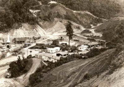 |
Stripping of the dam site has commenced. Pipe for the supply
line stacked in the middle distance over the stream bridge. The
stream diversion was not yet in place. |
 |
The stream diverted and the dam part finished - the valve tower at full height but
with no bridge. |
 |
The dam a little higher and the bridge to the valve tower
under construction - the aggregate bins for the tunnel concrete
lining have gone. The tree in the center has had too much root
disturbance and is near death. |
 |
The dam nearing full height in the second earthworks season |
 |
West abutment from the east - during site investigation |
Tunneling:
 |
Tunnel form at the downstream portal. The cement silo is over
the portal, the concrete mixer below that which discharged into
the concrete carriage vehicle in the tunnel. The mixer was fed
from a trolley mounted weigh hopper discharging onto a belt. The
three aggregate and sand hoppers are above. The central building
is the compressor shed. The air extract fan pipe can be seen
left of the portal, but has been disconnected. |
 |
Tunnelers - John Crabtree second from left. |
 |
Damaged photo of the tunnel junction form |
 |
Shifting the tunnel form |
 |
Taking pipe into the tunnel - taken from the tunnel portal -
the form is parked to the right |
 |
Placing pipe in the tunnel floor. |
Dam
Construction:
 |
Site stripping commencing - photo from upstream. The miners
adit into the manganiferous rock can be seen at the right. |
 |
Later in site stripping. |
 |
Downstream shoulder stripping |
 |
Core trench, covered drains from springs to the
pump well |
 |
Spring pump well |
 |
Right abutment shaping |
 |
Grout pipes to close pump wells |
 |
Filling |
 |
Down stream shoulder filling |
 |
|
 |
Piezometer tubes |
 |
Dam site Panorama |
 |
General view looking downstream - early in the fill placement |
 |
Compacting the filter drain - constructed by excavating a
trench through fill down to the last lift. |
 |
Filter drain construction |
 |
Filter drain construction with core placement
upstream |
 |
Filter drain construction - spillway shaft to the
left |
 |
The west abutment - soft sensitive alluvial
material required stripping her to get to competent rock and
weathered rock |
Valve Tower:
 |
Tunnel form being positioned at the upstream portal. The
inverted siphon of the interim supply pipe can be seen and the
under-floor permanent supply pipe |
 |
Link section from the upstream portal to the valve tower.
Inverted siphon on temporary supply pipe goes under. |
 |
Reinforcing tieing for the valve tower base |
 |
Shuttering for the valve tower base. |
 |
Rock anchor tendons. |
 |
Anchoring, pre-diversion. The weir supply pipe diverted
into the tunnel |
 |
Slipforming the valve tower underway |
 |
Valve tower top |
 |
Installing an intake gate valve |
 |
Concreting in an intake in the valve tower |
 |
Fixing the lake level markers to the valve tower |
 |
The bottom outlet pipe in place. |
 |
Pouring the tunnel plug in the valve tower base. |
 |
About to close the bottom outlet gate valve - from the left
Bruce Smithson, Don Wilson, John Crabtree, ?Keith Hay, Fergie
Schiska, ?(ARA photographer), ?. |
 |
The bottom outlet closed, Eric Scanlen facing the camera,
George Wyman on the right on the platform. |
 |
Installing the discharge valve on the bottom outlet. |
Valve
Tower Bridge:
 |
Foundations for the bridge pier |
 |
Pier bases |
 |
Pier construction from the tower. |
 |
Pier construction |
 |
Pier construction |
 |
Concrete pour for the pier |
 |
Launch beam |
 |
Delivery of a Tee beam for the valve tower bridge |
 |
Ditto |
 |
First beam ready to launch |
 |
First beam about to be lowered |
 |
Ditto |
 |
Third beam |
 |
Last beam in place |
Delivery
pipeline:
 |
Delivery pipe for the downstream portal to the
control structure under way |
 |
Supply pipe being laid |
 |
Control valve chamber inner form. Link structure
between the two tunnels in the background. Damaged photo. |
 |
Control valve being installed, pipe to right is
the overflow for an emergency drawdown. The valve has special
porting allowing fine control over part of the travel and
opening a large port area over the latter part for emergency
drawdown.. |
 |
Completed control structure |
Finishing:
Spillway:
 |
Spillway elbow shutter - in two halves second in
back right. |
 |
Spillway outside former |
 |
Stilling basin excavation |
 |
Stilling basin excavation |
 |
Stilling basin construction |
Spillway
model:
 |
The 1:40 scale hydraulic model of the spillway stilling basin
running at full capacity.
The model was built by the Authority staff and run at the
Auckland University Engineering School hydraulics lab. It was
used to confirm the bellmouth approach and fins were sufficient
to suppress vortexing in the down shaft, to check the choke size
needed at the bottom of the shaft, the pressures in the shaft,
the diversion tunnel transition, and the stilling basin form.
A large number of varieties of the stilling basin were tried,
mainly to get the teeth positioning and sizes right to control
the position of the hydraulic jump.
The shaft pressure checks were important as the transition
from the bellmouth to the vertical shaft was kept short to limit
the amount of double curvature shuttering that needed to be
built. With this a length of the shaft would run below
atmospheric pressure. If pushed too far the pressure would fall
to full vacuum and the flow might separate. The model confirmed
pressures stayed above full vacuum.
The choke at the shaft base limits the flow so the exit tunnel remains as free
surface flow. Otherwise the whole tunnel might fill expelling
air and run as a full pipe, increasing the flow beyond the
stilling basin capacity.
|
The Lake:
There were small areas of original bush in the lake area but most of
it had been cleared for farming between the wars. After the Council had
bought it for catchment land it had reverted to scrub - some of it high
kanuka by the 1970s. The vegetation had to be removed from the lake area
for water quality
reasons. The task was performed by staff. The initial task was cutting a
waterline road then felling the vegetation within the lake area and
burning it. The burning was done in stages. One fire got out of control
and burned a small area of bush above the waterline.
|